Astra G NCDR 1100 and cid investigation

evocarlos

Stupid Bollocks
Staff
collecting some info so far on the installation of the ncdr 1100 and cid

i will add text and rearrange this post later

the kit that i recived
WP_20141114_11_23_14_Pro (Medium).jpg

new dash trim and stereo cage
WP_20141031_19_39_54_Pro (Medium).jpg

the screen works :)
WP_20141114_11_18_44_Pro (Medium).jpg

on to the wiring the unit came with a full cab loom that i stripped out the parts i required
WP_20141026_15_50_37_Pro (Medium).jpg

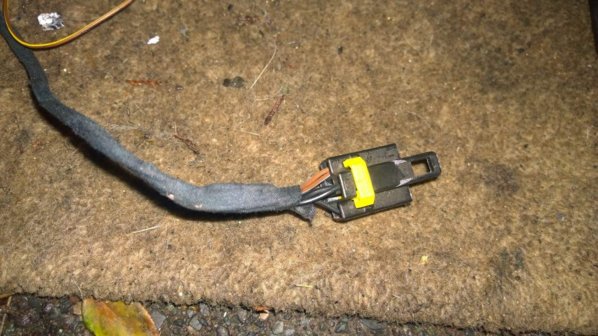
the ncdr series head units use a different plug like so
Radio Connector.JPG

i then bought an adapter loom to make a sort of plug and play adapter
WP_20141028_23_44_51_Pro (Medium).jpg

also on the ncdr plug are connections for the cid(12pin) and cid (32pin) and a plug for the cdc 4 disc changer
i already have the 4 disc changer so tapping in to its connections should make life easier
it also has one wire that goes to the phone unit plug that mast astras have behind the glove box
Mid Gid Cid Connector.JPG CID small connector.JPG

found the pinouts for the standard 32pin mfd plug so i could do a comparison
32pin mfd.JPG

after comparison i found that 6 wires need to be removed and 3 installed
image is left side (cid cab plug) right side is (mfd coupe plug)
left top has a green and white wire removed (marked with yellow dots)
left lower has an extra wire brown/grey that links to the brake pedal
right top needs 4 wires removing (marked with yellow dots) and then the green and white wires need to be installed (orange dots)
right lower just needs 2 pics removing(marked with red dots
32pin mid pins copy (Medium).jpg

next step is to figure out the main head unit plug the bottom 2 iso 8pin's are left the same

889ddc8s-960.jpg

i also found this image but it only shows the connection for the extra 12pin plug of the cid that i dont need due to having the part of loom from the cab
nn4e.jpg

more later :)

if anyone has tis and the wiring diagram for the cid / mfd and the head unit plugs info here would be good to help confirm the wiring :)
 

Attachments

  • WP_20141116_16_58_25_Pro (Medium).jpg
    WP_20141116_16_58_25_Pro (Medium).jpg
    185.3 KB · Views: 1,362
Last edited:

evocarlos

Stupid Bollocks
Staff
A14-36 - Connect - Notes

1 - A14-26 (1) - Power Control
2 - A14-26 (2) - F3.21 5A (+ 12V)
3 - - -
4 - A14-26 (4) - Weight
5 - A14-26 (5) - speed sensor signal
6 - - -
7 - A14-26 (7) - Power Antenna Control
8 - A14-26 (8) - F1.34 20A (+ 12V)
9 - A14-26 (9) - Rear Right -
10 - A14-26 (10) - Front right -
11 - A14-26 (11) - Front left -
12 - A14-26 (12) - Rear left -
13 - A14-26 (13) - Rear Right +
14 - A14-26 (14) - Front Right +
15 - A14-26 (15) - Front left +
16 - A14-26 (16) - Rear Left +


17 - X76 (2) - RGB Red +
18 - X76 (1) - RGB synchronization
19 - X76 (5) - RGB display
20 - - -
21 - A14-26 (26) - A15 (6) - CDC left + (white)
22 - A14-26 (22) - A15 (5) - A14-36 (36) - CDC total - (brown/black)
23 - A14-26 (21) - A15 (12) - CDC + Right (red)
24 - X76 (3) - RGB green +
25 - A14-26 (24) - A14-36 (33) - A15 (1) - X75 (11) - CAN-bus (white)
26 - A14-36 (4) - Weight
27 - A14-26 (19) - A15 (4) - Diagnostic output (brown/white)
28 - - -
29 - X1 (18) - Back-up alarm
30 - X76 (4) - RGB Blue +
31 - X76 (6) - RGB common -
32 - A14-26 (25) - A15 (7) - X75 (10) - High Speed CAN-bus (green)
33 - A14-26 (24) - A14-36 (25) - A15 (1) - X75 (11) - Slow CAN-bus (white)
34 - A14-26 (6) - Telephone MUTE
35 - A14-26 (23) - Telephone Audio + (blue)
36 - A14-26 (20) - Telephone audio - (brown and black)

A14-36 radio connector NCDR1100
A14-26 connector radio CDR500
A15 - connector CD-Changer
X75 LF terminal CID (32PIN)
X76 RF connector CID (12PIN)
X1 connector body front / rear
 
Last edited:

evocarlos

Stupid Bollocks
Staff
had another play with the ncdr and cid
cd player main lights off
WP_20141122_22_15_51_Pro.jpg

cd player lights on
WP_20141122_22_15_44_Pro.jpg

cd got jammed and would not exit it then broke its slef
so i went in to get my cd back lol
WP_20141122_22_28_42_Pro.jpg

plastic guide on the lower left had broken off
WP_20141122_22_28_51_Pro.jpg

the broken bit and where it came from
WP_20141122_22_40_48_Pro.jpg

good job i have spares :)
WP_20141122_22_41_25_Pro.jpg

also found an old blue tooth gps devce that has a plug may come in handy for the sat nav if i can give the gps device 5v supply
WP_20141122_23_13_37_Pro.jpg

all the other functions were tested only thing left was to get the 4 disc cd changer working
a video
 

evocarlos

Stupid Bollocks
Staff
steps to change the leds in the face
WP_20141203_22_46_18_Pro.jpg

2 screws in the top rear of the case
WP_20141203_22_48_51_Pro.jpg

cut the warranty void sticker and pop the top
WP_20141203_22_47_01_Pro.jpg

same for the bottom once the top and bottom are off there are hooks on the front to unclip it
WP_20141203_22_51_16_Pro.jpg

and its off
WP_20141203_22_52_52_Pro.jpg

after removing the screws on the pcb it comes apart
WP_20141203_22_56_34_Pro.jpg


WP_20141203_22_56_45_Pro.jpg

knobs off and nuts undone to get to the pcb and the led's
WP_20141203_22_59_09_Pro.jpg

testing for different colors red for the flashing code lamp
WP_20141204_00_02_50_Pro.jpg

red for the what i think is the phone buttons
WP_20141204_00_03_27_Pro.jpg

and green next to it
WP_20141204_00_03_17_Pro.jpg

removing all the amber leds one side at a time
WP_20141203_23_55_02_Pro.jpg

all off
WP_20141204_00_00_11_Pro.jpg

cleaning the pads with desolder braid
WP_20141204_00_18_57_Pro.jpg
 
Last edited:

evocarlos

Stupid Bollocks
Staff
30 new white smd leds
WP_20141204_17_29_04_Pro.jpg

all on :)
WP_20141204_18_15_41_Pro.jpg

the plastics were all washed in hot water with fairy liquid
WP_20141204_19_00_39_Pro.jpg
 
Last edited:

evocarlos

Stupid Bollocks
Staff
have been trying to get the steering wheel controls working

think i found out why
the adapter cable i bought was for an aftermarket wheel controller so it had missing wires and wires in the wrong places :confused:
WP_20141207_20_34_53_Pro.jpg

i b*****dized a wheel control adapter i had about and fitted the wires in
WP_20141207_21_01_34_Pro.jpg
 

evocarlos

Stupid Bollocks
Staff
steering wheel controls working but the next and previous track buttons are in reverse

not sure on the grey trim :confused:
WP_20141207_23_03_00_Pro (Medium).jpg

cid.JPG
 

Djice74

Member
steps to change the leds in the face
View attachment 58048

2 screws in the top rear of the case
View attachment 58046

cut the warranty void sticker and pop the top
View attachment 58047

same for the bottom once the top and bottom are off there are hooks on the front to unclip it
View attachment 58044

and its off
View attachment 58043

after removing the screws on the pcb it comes apart
View attachment 58042


View attachment 58041

knobs off and nuts undone to get to the pcb and the led's
View attachment 58040

testing for different colors red for the flashing code lamp
View attachment 58052

red for the what i think is the phone buttons
View attachment 58050

and green next to it
View attachment 58051

removing all the amber leds one side at a time
View attachment 58054

all off
View attachment 58053

cleaning the pads with desolder braid
View attachment 58049
 

Djice74

Member
Hi mate was searching on the web for information on this upgrade but this is the only recent post available and the work u are doing is top dollar.
I ve got a zafira gsi with the same cid u have and have the ncdr 1100 coming next week is it going to be plug and play with the ISO adapter? Be great if you could help I will upload some photos in a bit to show what I'm running. Basically I mostly want the board computer information running.

Thanks Andrew
 

evocarlos

Stupid Bollocks
Staff
hey Andrew
the wiring is fairly easy the master plug on the ncdr is what controls the screen
the issue is the ncdr1100 and cid screen are paired together so you need both items from the car it came out of unless the screen has been divorced before removal the issue then is it needs tech 2 to be married back together

i am also not finished with the install i still need to get the steering wheel controls to function correct and add the wires to the cd changer and phone unit then i need to get the gps/gsm aerial
 

evocarlos

Stupid Bollocks
Staff
the ncdr2013
aka ncdr 1100 with a 4 disc cdc double stacked lol
WP_20141220_15_06_01_Pro.jpg

the plug i got with the kit was cut up i also go no cage
WP_20141220_16_24_34_Pro.jpg

spares for mine if the case need be :)
WP_20141220_16_24_57_Pro.jpg

original cage modded to take the navi plug
WP_20141220_18_30_14_Pro.jpg

and then the gps aerial plug
WP_20141220_18_41_20_Pro.jpg
 
Top